433 MHz RC plane Prototype
แสดงบทความที่มีป้ายกำกับ drone แสดงบทความทั้งหมด
แสดงบทความที่มีป้ายกำกับ drone แสดงบทความทั้งหมด
วันจันทร์ที่ 23 พฤษภาคม พ.ศ. 2565


วันจันทร์ที่ 16 พฤษภาคม พ.ศ. 2565

วันพฤหัสบดีที่ 1 สิงหาคม พ.ศ. 2562
Low cost FPV Tiny Whoop with SilverWare ACRO mode enabled

Instruction "Low cost FPV Tiny Whoop with SilverWare ACRO mode enabled" will describe how to make low-cost DIY FPV mini quadcopter by using cheap spare parts of brand name drones in the market to re-fabricate to be DIY performance mini quadcopter.The result was very surprising,it's making the big brand expensive drone to be shamed.It flies very stable even in the outdoor windy air.The coreless motors 7x16 are more powerful than 6x14 of regular Tiny whoop.Easy and durable for pilots from beginners who need FPV training to Pros who need Acro mode flying.
Difficulty : Easy
Cost : 40-60 USD. (excluded Transmitter,FPV gogle)Materials
1. Bwhoop B-03 or Eachine E011 shell body.

2. Bwhoop B-03 or Eachine E011 propellers set.

3. Bwhoop B-03 or Eachine E011 716 coreless motors set.

4. Bwhoop B-03 Pro board or Eachine 010c with ultitude hold.

5. 1s Lipo Battery.

6. FPV camera.

7.FPV goggle.

8. ST-link V.2

9. Bwhoop B-03 Pro complete set.(Optional for non-RC guys)

10. Mutiprotocol Tx module.(For Frsky,Flysky,Turnigy,other PPM Tx)

Tools
2. Soldering wire
3. Soldering paste
4. Plier
5. Hot glue gun
6.Hot glue rods
Making process
1.Flashing controller board with Silverware.
You can follow this web link(https://www.rcgroups.com/forums/showthread.php?2876797-Boldclash-bwhoop-B-03-opensource-firmware).They describe how to do in deeply detail, see this video clip for real flashing.
2.1. Assemble bodyshell,motors,propellers together.
Be carefull to install corrective motors at the right positions as showing figure.

2.3. Fixing FPV camera above controller board with shock absorber tape and rubber band.
Connect power cable directly to available port on controller board.
3.Multiprotocol Tx module modification and binding.(For Frsky/Flysky/Turnigy Tx)
3.1 The cheap commercial Multiprotocol Tx module's operating range has just +/- 5m.only.This range is too short to fly in Acro mode.To extend range,it can be modified by connecting hard fixed attenna of Multiprotocol module with 2.4G RP-SMA 2dB antenna by soldering two wires at antenna +/- poles.The range would be extended to +/- 10m.


3.2 Using unused back module case for containing Tx module.
3.3 See video clip which illustrates how to set ACRO/LEVEL mode.
Flight test
วันพฤหัสบดีที่ 14 มีนาคม พ.ศ. 2562
How to build DIY FPV mini Quadcopter

Instruction "How to build DIY FPV mini Quadcopter" will explain how to make low-cost DIY FPV mini Quadcopter by using household material and cheap electronic parts,simple soldering method and general basic tools.
Difficulty : MediumCost : around 55 USD. (excluded Transmitter)
Materials
1. Ice cream stick,10 mm.width.

2. Meat ball wooden stick


4. 1 - Cable tie(small)

5. Rubber band(small)

6. 1 - Tiny brushed flight controller

2 - 720 CCW coreless motors

8. 2 - 8520 CW blde propellers
2 - 8520 CCW blde propellers

9. 1 - Tiny Frsky/Flysky/DSM receiver module

10. 1 - Tiny FPV camera 700TVL 5.8GHz

11. 1 - Low ESR 470microF 25V

12. 1 - Male battery connector


Tools
1. Soldering gun
2. Soldering wire
3. Soldering paste
4. Plier
5. Hot glue gun
6.Hot glue rods
7.UHU por glue
Making process
1. Cutting four A,B,C and D type of ice cream sticks as the drawing.

3.Cutting future board as the drawing.

5.Making camera base by future board,using wooden rod for camera rubber band fastening.
6.Fixing base on X main frame by hot glue gun.(see picture)

8.Soldering battery cable connector to flight controller main power port.
9.Attach flight controller on X main frame by shock absorbing glue tape.
10.Wiring and soldering micro receiver with flight controller.
11.Wiring and soldering four coreless motors as following layout.
12.Wrapping up electrical tape on every coreless motors to prevent heat glue melting.
13.Using cable ties to fix every motors in their places.
14.Glueing every 720 coreless motors by hot glue gun.
15.Updating firmware of flight controller by Betaflight App.Adding AUX switches to select flight mode-Angle,Acro and Air mode.Normally,do not need to adjust PID setting and motor setting.The micro receiver signal can be set to PPM or SBUS.If the controller can be armed ,it's ok.If not ,problems can be solved by search engine or YouTube.
Flight test.
https://www.ebay.com/e/_electronics/shop-all-excellent-refurbished?mkcid=1&mkrid=711-53200-19255-0&siteid=0&campid=5338035940&toolid=20014&customid=&mkevt=1
วันจันทร์ที่ 20 กุมภาพันธ์ พ.ศ. 2560
How to Control Tracked Robot Via Joystick NRF24L01 Module Arduino Part2 Rx

The instruction will describe the method how to build Receiver(Rx) on Tracked Robot for Transmitter(Tx) in the instruction "How to control Tracked Robot via Joystick NRF24L01 Module Arduino Part1 Tx".
More information : www.instructables.com
Materials & Tools
Materials
1. 1 - Arduino controller - Nano

2. 1 - NRF24L01 module

3. 1 - Socket adapter for NRF24L01(For protect & stabilize NRF24L01 module)

4. 1 - LED 5 mm.

5. 1 - Resistor 1 kOhm. 1/4 watt.

6. 1 - Capacitor 0.1 microF /50V.

7. 1 - Capacitor 1 microF /50V.
8. 1 - Capacitor 100 microF /50V.
9. 1 - Diode 1N4001
10. 1 - 7805 IC Regulator 5V.
11. Dupont cable

12. Female pin header

13. 1 - L298N Arduino module

14. Electrical wires

15.Heat shrink tube 1.5 - 10 mm.

16. PCB - DIY circuit board

17. Battery Lipo 7.4 V. 500-1000 mAh

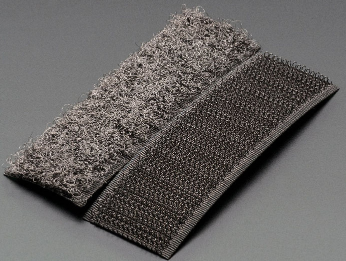
18. Velcro tape
19. Tamiya track and wheel set

20. Tamiya dual geared box

21. Tamiya plastic perforated plate

22. 2 - pairs of JST plug

Tools
1. Soldering gun.
2. Soldering wire.
3. Soldering paste.
4. Screw driver.
5. Plier.
6. Hot glue gun.
7. Miscellaneous screws ,bolts and nuts.
Electronic parts Installation

DIY PCB Building
Connecting electronic parts on PCB according to circuit diagram and solder them.

Arduino Nano pin to L298N
Pin No :
3 - ENA
4 - IN1
5 - IN2
6 - ENB
7 - IN3
8 - IN4
GND - GND of L298N
L298N module
Vcc - Battery positive pole
GND - Battery negative pole - GND of NANO
MotorA - Left motor
MotorB - Right motor
nRF24L01 module Socket Adaptor to Arduino Nano
Pin No :
Vcc - 5 V. supply (Do not connect 5V. directly to nRF24L01 module,it's supplied only 3.3V.)
GND - GND
CE - 9
CSN - 10
SCK - 13
MO - 11
MI - 12
IRQ - 2
*If you have communication problem,you can change connection from pin 13,11,12 to pin SCK,MOSI,MISO of Nano programming pins.
*It's necessary to add 0.1 microF to nRF24L01 module pin Vcc/GND because the module needs stable current and voltage.

Arduino sketch and Library :

1.Down load file .ino and library zip file GitHub.
2.Add library zip file to Arduino IDE.You will see new library RF24-master in Examples menu.
3.Before using new nRF24L01 modules,we shall burn the modules by uploading default sketch pingpair and GettingStarted for tuning up frequency otherwise it will has uncommunication problem.(Use another Arduino Nano and nRF24L01 modules for pairing)
4.After succeed matching the frequency ,we can upload Rx sketch Rx_2CH_robot_V13_ NANO_for_remote_NANO_V2_public2 to Nano controller.
5.Test Receiver(Rx) with Transmitter(Tx).See serial monitor showing the print out data as attached video clip.


สมัครสมาชิก:
บทความ (Atom)