
This is the continued instruction of "How to hack RC CAR via Arduino nRF24L01 2.4G Transmitter(Tx) Part1"
The instruction will advice how to hack AM/FM RC car via 2.4 GHz Arduino nrf24l01 module.
Materials & Tools
Materials
1. 1 - Arduino UNO
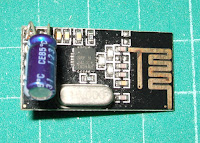
2. 1 - NRF24L01 module
3. 1 - Socket adapter for NRF24L01

4. 4 - LED 4 mm. (1-couple of White and 1-couple of Red)
5. 2 - Resistor 1 kOhm. 1/4 watt.
6. 1 - Capacitor 0.1 microF 16V.
7. 3 - Capacitor 1 microF 16V.
8. 1 - Capacitor 220 microF 20V.
9. 1 - L293D H-bridge dual motors drive IC

10. 1 - 16-Pins DIP IC Sockets Adaptor(For L293D)

11. Dupont cables

12. Male pin header

13. Female pin header

14. Dupont Jumper Cable Housing Male Pin Connector

15. Dupont Jumper Cable Housing Female Pin Connector

16. Heat shrink tube 2.5 mm.

17. PCB - DIY circuit board

18. Battery Lipo 7.4 V. 1000 mAh. (2 cell)

19. Male JST Battery Pigtail

20. 1 - RC car toy (H-bridge dual motor radio control)

Tools
1. Soldering gun.
2. Soldering wire.
3. Soldering paste.
4. Screw driver.
5. Plier.
6.Hot glue gun.

7.Fixing material
Electronic parts installation & DIY shield


Arduino UNO to L293D (Make DIY shield)
UNO pin - to - L293D pin
3 - 2
4 - 7
6 - 15
7 - 10

L293D pin
1 - 5V. supply(+Capacitor 1 mF/16V)
3 - Steering Motor
4 - GND
5 - GND
6 - Steering Motor
8 - 7.2 V. Batt.+(+Capacitor 220 mF/20V)
9 - 5V. supply(+Capacitor 1 mF/16V)
11 - Driving Motor
12 - GND
13 - GND
14 - Driving Motor
16 - 5V. supply(+Capacitor 1 mF/16V)
nRF24L01 module to Arduino UNO
pin No :
Vcc - 5 V. pin(+Capacitor 0.1 mF/16V)
GND - GND
CE - 9
CSN - 10
SCK - 13
MO - 11
MI - 12
IRQ - 2

*If you have communication problem,you can change connection from UNO pin 13,11,12 to pin SCK,MOSI,MISO of UNO programming pins.
*It's necessary to add 0.1 microF/16V to nRF24L01 module pin Vcc/GND the module needs stable voltage.
+Solder a solid copper wire on nRF24L01 module antenna can improve remote range more.
*Soldering all devices carefully ,use enough large wire.Making good ground otherwise it will has ghost input signal.
*Before connecting main supply,check out to find short circuit points on DIY shield. Otherwise it will smoke.(Be careful of Lipo battery ,high current supply , short contact will spark fire)
Arduino sketch and Library :
1.Down load RC_dual_motors_L293D_relay_RxV4-public.ino file from GitHub.
2.Assuming RF24-master library has been added ,frequency matching ok.Now ready to upload Rx sketch to Arduino receiver.
(If you have problem,go to visit website https://arduino-info.wikispaces.com/Nrf24L01-2.4GHz-HowTo for more information)
3.If installation works good,it shall run fine.But if serial monitor do not show anything as the video clip,back to check out hardware and electronic parts installation.


ไม่มีความคิดเห็น:
แสดงความคิดเห็น