This instruction introduce to hack 3-Channel RC transmitter(Tx).The standard remote control of RC car and boat.
More information : https://www.instructables.com/id/How-to-Hack-RC-Car-Transmitter-Via-24-GHz-NRF24L01/
Materials & Tools
Materials
1. 1 - Arduino controller - Nano
2. 1 - NRF24L01 module with or without SMA anttenna

3. 1 - Socket adapter for NRF24L01(For protect & stabilize NRF24L01 module)

4. 1 - LED 4 mm.(Option)
5. 1 - Resistor 1 kOhm. 1/4 watt.(Option)
6. 1 - Capacitor 0.1 microF /50V.
7. 1 - Capacitor 1 microF /50V.
8. 1 - Capacitor 100 microF /50V.
9. 1- Diode 1N4001
10. 1 - 7805 IC Regulator 5V.
11. Dupont wires.

12. Female pin header

13. Dupont Jumper Cable Housing Male Pin Connector

14. Dupont Jumper Cable Housing Female Pin Connector

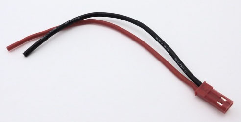
15. Male JST Battery Pigtail
16. Heat shrink tube 1.5 - 10 mm.

17. Velcro tape

18. PCB - DIY circuit board

19. Battery Lipo 7.4 V. 1000 mAh

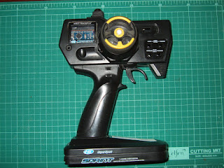
20. Unused 3-Channel RC transmitter(Pistol type with Steering wheel)

Tools
1. Soldering gun.
2. Soldering wire.
3. Soldering paste.
4. Screw driver.
5. Plier.
6. Hot glue gun.
7. Epoxy glue.
8. Screw,bolts,nuts.
Body modification,Electronic parts installation
Body modification & DIY PCB


1. Open transmitter body up,remove unnecessary PCB ,leave Steering potentiometer , ESC potentiometer and Auxiliary switch for hacking.
2. Make DIY PCB according to circuit diagram.(See pin connection below)
*Soldering all devices carefully ,use enough large wire.Making good ground.
3. Cut off plastic body to open a hole for Nano USB.

4. Modify battery compartment by cutting all plastic fins for more clear room.Paste Velcro tape on battery and compartment to fix battery in place.

6. Connection wiring between DIY PCB , Potentiometers , power switch and battery terminal.
*Before connecting main supply,check out to find short circuit points on DIY PCB.Otherwise it can smoke and burn everything.(Be careful of Lipo battery , it's high current supply , short contact will spark fire)

Arduino Nano to Pistol Transmitter Connection
pin No :
A3 - Steering servo potentiometer signal o/p
A4 - ESC potentiometer signal o/p
D4 - Auxiliary switch o/p
nRF24L01 module Socket adaptor to Arduino Nano
pin No :
Vcc - 5 V. supply (Do not connect 5V. direct to nRF24L01 module,it's supplied only 3.3V.)
GND - GND
CE - 9
CSN - 10
SCK - 13
MO - 11
MI - 12
IRQ - 2
*If you have communication problem,you can change connection from pin 13,11,12 to pin SCK,MOSI,MISO of Nano programming pins.
*It's necessary to add 0.1 microF to nRF24L01 module pin Vcc/GND because the module needs stable current and voltage.Also solder a small wire at the antenna to increase control range.
Software installation
Arduino sketch and Library :
1.Down load library zip file and sketch files .ino from GitHub.
2.Add library zip file to Arduino software.(After added you will see new library RF24-master in Examples menu.)
3.Before using new nRF24L01 modules,we shall burn the modules by uploading default sketch pingpair and GettingStarted for tuning up frequency otherwise it will has uncommunication problem.(Use another Arduino Nano and nRF24L01 modules for pairing)
4.After matching the frequency ,we can upload sketch file Tx_Board V7-public.ino to Arduino Nano transmitter.
- Steering Potentiometer will send code between 150 - 910 at 4.5V. if voltage change Potentiometer will send another code range it's necessary to maintain voltage.Another transmitter brand send different code,it has to be checked before updating sketch.
- ESC Potentiometer will send code between 170 - 900 at 4.5V. if voltage change Potentiometer will send another code range , it's necessary to maintain voltage.Another transmitter brand send different code,it has to be checked before updating sketch.
Both code have to be divided by 10 to reduce value to two digit data before sending on radio.(See detail in attached sketch)
5.The sketch serial monitor will not show anything as video clip.We have to build receiver(Rx) on the car.Go to next instruction"How to Hack RC Car Receiver via 2.4 GHz NRF24L01 Arduino Part 2 Rx+Servo+ESC"


ไม่มีความคิดเห็น:
แสดงความคิดเห็น